Power five prevention system is used for bus grounding maintenance
Auxiliary power 10kV / 6kV bus maintenance interlocking will form interlocking between incoming cabinet, liaison cabinet, transformer feeder cabinet and bus grounding knife
Only after the incoming cabinet, liaison cabinet and transformer feeder cabinet are disconnected, the key can be released from the exchange box to unlock the bus ground knife lock, so as to ensure the safety of maintenance personnel.

Interlocking application of electric power five prevention system in electrostatic precipitator
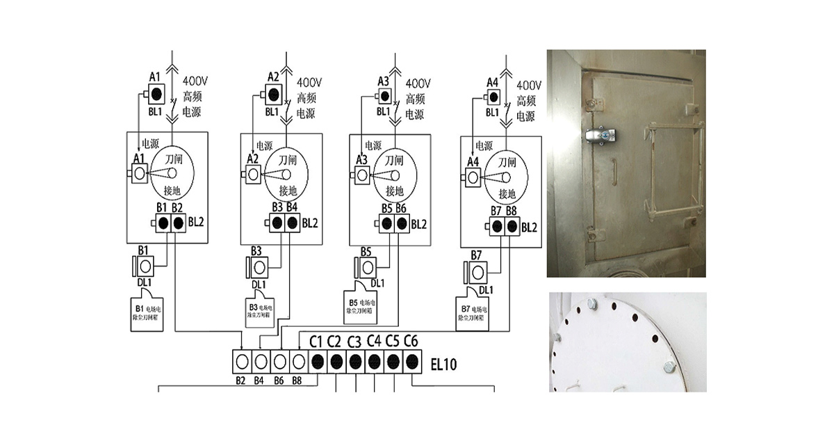
If you directly enter the manhole door of the electrostatic precipitator room without disconnecting the 400V power switch or grounding discharge, there will be a risk of entering the charged interval by mistake. If a set of mechanical interlocking is installed on the 400V switch, rectifier transformer ground knife and manhole door according to the normative logic, the problem of entering the charged interval by mistake in the electrostatic precipitator room can be well solved.
Description of interlocking scheme:
1. When each 400V high-frequency power switch is operated to the power-off position, the keys A1, A2, A3 and A4 in each latch lock can be pulled out, and the locking switch is in the power-off position;
2. Insert the keys Al, A2, A3 and A4 into each grounding switch to unlock the grounding knife. When operating the grounding knife to the closing position, turn all keys B on BL2 lock to lock the grounding knife in the closing position;
3. Use the keys BL, B3, B5 and 87 to open the doors of each knife switch box and start the maintenance work;
4. When it is necessary to enter the dust collector for maintenance, insert all keys 82, 84, 86 and B8 into the exchange box, exchange key C, and then open the manhole door to start maintenance.

Interlocking application of power five prevention system in maintenance of dry type transformer
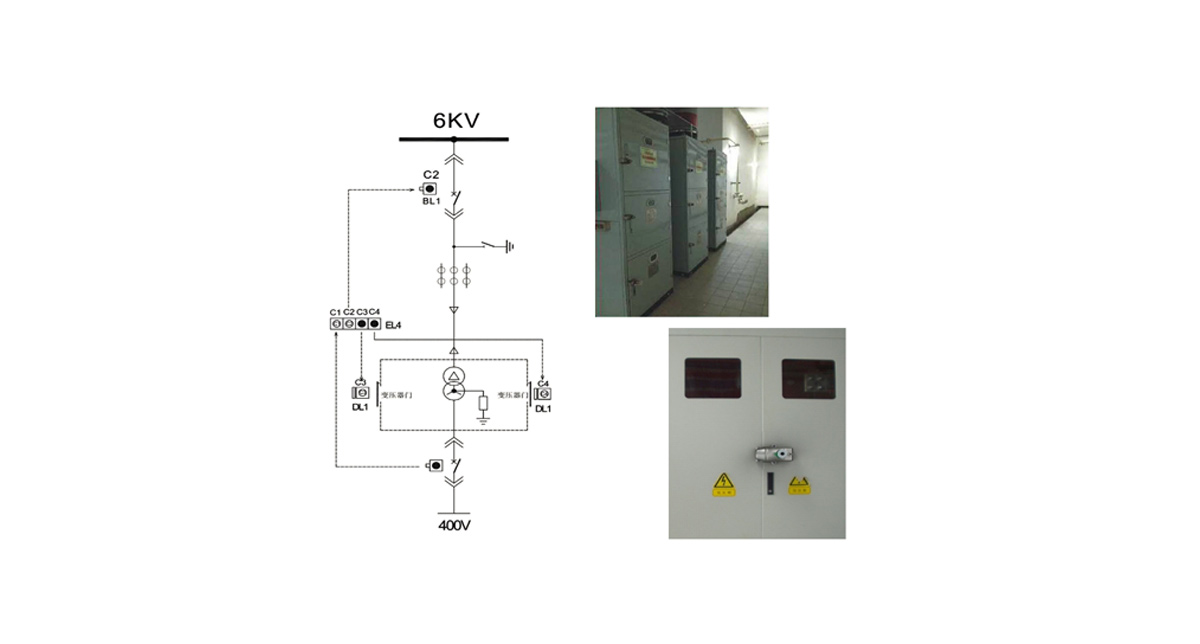
When the dry-type transformer is overhauled, if the high and low voltage side switches of the dry-type transformer are not disconnected, it will be very easy to enter the live interval by mistake. This potential safety hazard can be well solved by mechanical interlocking.
Description of interlocking scheme:
1. Disconnect the 400V circuit breaker, pull it to the test position, rotate and pull out the key C1 of the mechanical lock on the 400V circuit breaker, and the 400V circuit breaker will be locked in the disconnected state.
2. Disconnect the 6kV circuit breaker, pull it to the test position, rotate and pull out the key C2 of the mechanical lock on the 6kV circuit breaker, and the 6kV circuit breaker will be locked in the disconnected state.
3. Insert the above C1 and C2 keys into the two for two key exchange box to exchange the keys C3 and C4.


